
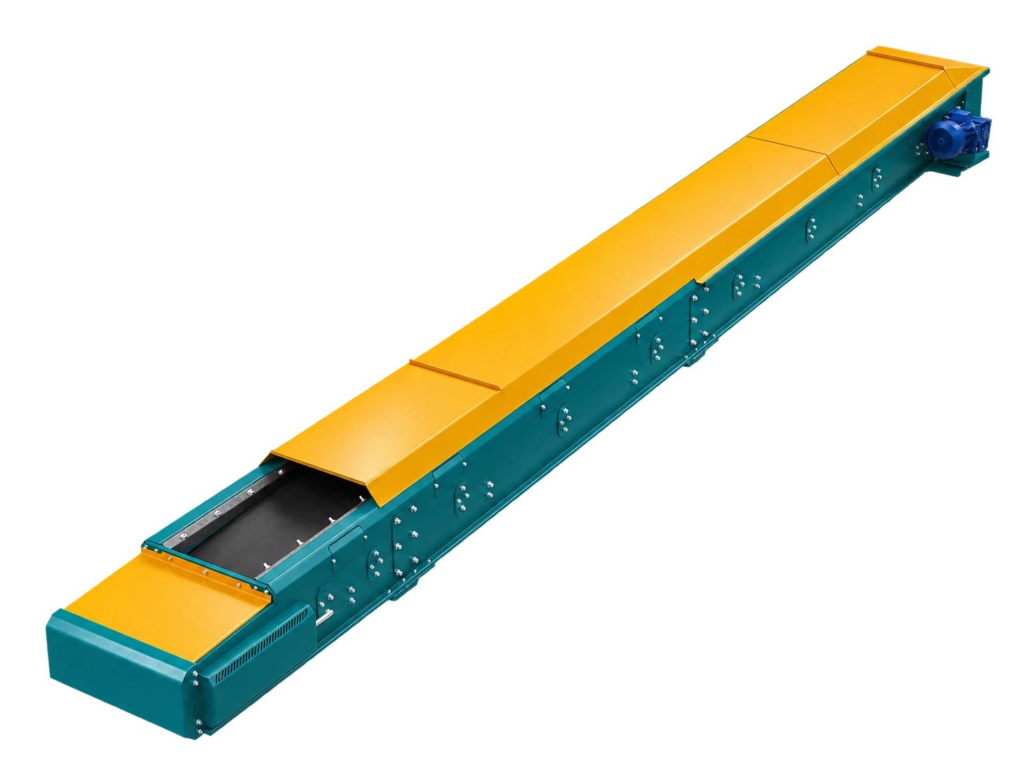
How does a belt conveyor work, and where does selection start?
A drive pulley moves the belt. Carrying idlers support the belt and load, while return idlers carry the empty belt back. For bulk material, carrying idlers commonly shape the belt into a trough. Rulmeca states that roller selection must suit belt width and speed as well as the material and environment.
Selection begins with the duty, not a machine dimension: what material must move between which points, at what minimum, normal and peak flow? Is operation continuous or intermittent? Which machines connect at loading and discharge?
Why do tonnes per hour not define capacity alone?
Tonnes per hour is mass flow; the belt must carry material volume. Volumetric flow equals mass flow divided by bulk density. As a purely illustrative calculation, 20 t/h occupies 20 m³/h at 1.0 t/m³, but 40 m³/h at 0.5 t/m³. The same mass flow requires twice the volume in the second case.
Bulk density should reflect the loose, compacted or aerated state actually presented to the conveyor, not an unrelated reference value. Record minimum, normal and peak rates separately. CEMA treats belt capacity and belt selection as distinct fundamentals of bulk-conveyor design.
How are belt width and speed selected together?
Capacity depends on usable load cross-section multiplied by belt speed. Cross-section changes with belt width, trough geometry, the shape formed by the material and safe edge clearance. Rulmeca explains that troughed carrying arrangements can provide more material area at the same width and speed, while idlers must support the duty.
More speed may raise volumetric flow, but is not automatically better. Dust, spillage, product degradation, loading impact and discharge behaviour must be reassessed. Maximum lump and full size distribution must fit the belt and trough. Width, speed, trough and feeding form one design problem.
Which material properties change the decision?
A material name is only a start. Record bulk density, largest lump and gradation; moisture, cohesion, abrasiveness, temperature and dust tendency. Wet cohesive product can cling to the return belt; abrasive lumps can challenge chutes, belt cover and liners; very fine product can become airborne at transfers.
Where seasons or recipes change conditions, provide realistic extremes as well as averages. These inputs guide project-specific assessment of belt cover, cleaning, sealing, impact support and enclosure.
Why is there no universal maximum incline?
Draw start and finish elevations, horizontal distance and the true conveying path. As incline increases, material may slide or roll back and usable cross-section can change. The result depends not only on angle but also particle shape, moisture and friction, belt surface, acceleration and loading.
There is therefore no single maximum angle for every material. Smooth, patterned or cleated belts, and alternative principles such as a bucket elevator for steep lifting, need comparison using material tests and manufacturer data.
How do loading and discharge limit the line?
A conveyor rating does not correct an erratic feeder. The loading point should place material near the belt centre in a controlled stream compatible with belt direction. Martin Engineering notes that free-falling material creates impact and turbulence, and that a settling zone depends on belt width and speed, chute width, airflow, bed depth and largest lump.
The discharge chute and downstream machine must accept the same flow and particles. Define what happens when a crusher, screen, silo or packaging line stops, including overflow detection, controlled shutdown and restart sequence.
What project data should be ready before a quotation?
Provide the material and a representative sample; bulk density; size distribution and largest lump; moisture, cohesion, abrasiveness and temperature; minimum-normal-peak flow; daily duty; start and finish elevations; horizontal distance; loading and discharge points; indoor or outdoor environment; dust control; existing interfaces and maintenance access.
Mark unknown values for measurement rather than turning estimates into facts. The manufacturer can then size the drive, take-up, pulleys, idlers, belt and supporting structure from verified inputs.
Safety and the limits of this guide
Belt-pulley contacts, idlers, drives and transfer zones create pinch and entanglement hazards. Guards, emergency stops, access and warnings require a site risk assessment and applicable rules. Before inspection, cleaning, take-up adjustment, tracking or clearing a blockage, follow manufacturer instructions and the site procedure; authorised personnel must isolate energy and verify a safe state. OSHA 1910.147 requires an energy-control programme where unexpected start-up or stored energy can injure workers during servicing.
This article is not an operating, maintenance or final-sizing instruction. It states no capacity, belt width, speed, incline, motor power, dimension, certification or performance value for any İnovate model.
Sources
Sources were checked on the article publication date. These are general technical references, not documentation of İnovate product specifications.
- CEMA — ANSI/CEMA Standards for Belt Conveyors and Bulk Materials
- Rulmeca — Project and Design Criteria for Belt Conveyors
- Rulmeca — Upper Carrying Troughing: Selection Criteria
- Martin Engineering — Transfer Point Load, Settling and Stilling Zones
- OSHA — Control of Hazardous Energy (Lockout/Tagout), 29 CFR 1910.147
